

Best MCCB Choices for Safe and Efficient Power Distribution
2026-11-02
Selecting the right MCCB isn't just about tripping curves and kA ratings—it's the quiet backbone of every safe and efficient power distribution system. Whether you're upgrading an aging panel or designing a new facility, the choices you make today ripple through performance, downtime, and long-term costs. But with so many brands and specs claiming to be 'the best,' how do you cut through the noise? That's where ETEK enters the conversation—not with generic promises, but with a practical lens on what truly matters in modern circuit protection. In this guide, we'll unpack the key factors, avoid common pitfalls, and share real-world insights to help you choose an MCCB that doesn't just meet code—it earns its place in your distribution network.
How to Match Breaking Capacity to Your Fault Current Without Overpaying
Most switchgear ends up with a breaking capacity far above what the site actually needs, simply because someone used a worst-case utility figure and never recalculated at the equipment terminals. Start with a real available fault current study: account for transformer impedance, cable length, and motor contribution. That number, not the infinite bus value at the transformer secondary, is what your breaker really has to interrupt.
Once you know the genuine fault current, choose a breaker whose interrupting rating sits just above that value with a small safety margin, usually 10–15%. There is no technical benefit in jumping to 65 kA or 100 kA if your calculated duty is 22 kA. Oversizing only adds cost and can make coordination harder because higher-rated breakers often have different trip characteristics.
If the calculated fault current is close to a standard rating, look at current-limiting devices upstream or series-rated combinations that have been tested together. These options can reduce the required downstream breaking capacity without compromising protection. Always verify the series rating with the manufacturer’s tested combination, and keep the documentation on site for inspections.
Thermal-Magnetic or Electronic Trip Units for Your Load Profile
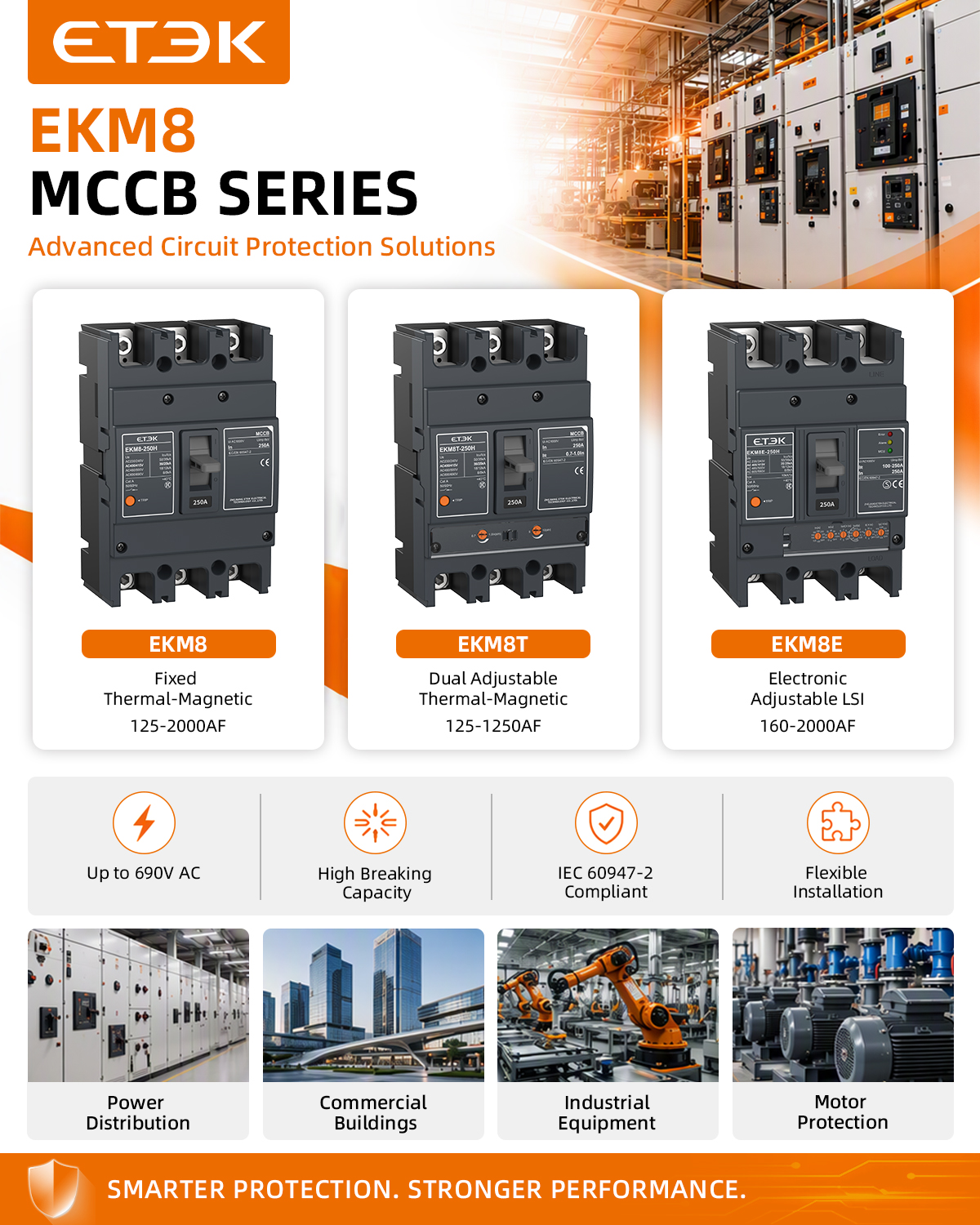
Choosing between thermal-magnetic and electronic trip units often comes down to how predictable your load really is. Thermal-magnetic devices use a bimetallic strip for overloads and an electromagnet for short circuits, which works fine for steady, resistive loads like lighting or heating panels. But if your equipment draws inrush currents, cycles frequently, or carries harmonics, the fixed response curve can lead to nuisance tripping or delayed protection when you least expect it.
Electronic trip units, by contrast, let you shape the protection curve around the actual behavior of your load. You can adjust long-time, short-time, and instantaneous settings, often with tighter tolerances and better repeatability. That matters for motors, transformers, and mixed loads where startup surges are normal but real faults still need fast isolation. Some electronic units also offer ground-fault detection, metering, and communication, which can simplify troubleshooting later.
The right choice isn't about one being universally better—it's about matching the trip unit to the load profile you actually have. If your system is simple and stable, a thermal-magnetic breaker may be all you need and easier to maintain. If your loads vary, restart often, or need selective coordination upstream, an electronic trip unit gives you the flexibility to avoid downtime and protect equipment without guesswork.
Selective Coordination Tricks That Prevent Whole-Panel Blackouts
One of the biggest mistakes in panel design is treating every breaker like it should trip at the same speed. If a downstream branch circuit faults, and the upstream main breaker is just as fast, both open—and you lose power to an entire section of a building. Selective coordination flips that logic: you deliberately make the protective devices closest to the fault faster and more sensitive, while giving upstream devices a short delay or higher instantaneous threshold. The trick is not just picking bigger breakers, but aligning their time-current curves so there's a clear 'clearing zone' where only the nearest device reacts. For example, a 20 A branch breaker might have an instantaneous trip at 200 A, while the 100 A feeder breaker feeding it has its instantaneous pickup pushed to 1,200 A—well above the branch fault current but still below the feeder's own short-circuit level.
Zone-selective interlocking (ZSI) is the hidden tool many designers overlook. Instead of relying on fixed pickup settings alone, ZSI wires the downstream and upstream breakers together so they can talk during a fault. When the branch breaker sees a high fault current, it sends a restraint signal to the upstream breaker, telling it to hold off on tripping for a few cycles. If the branch breaker clears the fault, the upstream breaker never moves. If the fault is between them, no restraint signal arrives, and the upstream breaker trips immediately. This works especially well in hospitals, data centers, and industrial plants where nuisance tripping of a main panel is unacceptable. The wiring is simple—usually a twisted pair between the trip units—but the coordination benefit is massive.
Sometimes the cheapest coordination trick is using current-limiting fuses or breakers at the branch level. These devices chop the fault current so fast that the peak let-through energy stays below the threshold that would cause an upstream breaker to begin its trip sequence. Pair that with a short-time delay on the upstream breaker (say 0.1 to 0.3 seconds) and you get a reliable time gap. In many commercial panels, simply setting the main breaker to 'I²t out' and the branch breakers to 'instantaneous' solves 80% of coordination complaints. But don't guess—run a selective coordination study with actual fault currents at each bus. A few hours of calculation can prevent a single overloaded cord from knocking out an entire floor.
Why Ambient Temperature Derating Is the Silent Killer of MCCB Performance
MCCB datasheets typically list current ratings under a neat, laboratory-friendly 40°C ambient. But real installations rarely cooperate. Inside a packed distribution board, trapped heat from adjacent breakers, cables, and even sunlight on an outdoor enclosure can push the local temperature well past that baseline. The result is a quiet erosion of trip thresholds: a breaker rated for 100 A at 40°C may effectively become an 85 A device at 55°C, not because it fails, but because the thermal element reaches its deflection point sooner. No alarm sounds. No fault appears. The breaker simply stops delivering the capacity the design assumed.
This silent drift compounds in systems with marginal conductor sizing or harmonic loads. An engineer checks the drawings, sees a 125 A MCCB feeding a 120 A load, and assumes headroom. But if the enclosure averages 50°C, the real trip curve shifts enough to cause nuisance tripping under conditions the drawings never predicted. Worse, because derating tables are often buried in fine print, the performance loss remains invisible until an entire production line goes dark on a hot afternoon. The breaker isn't defective; it's operating exactly as physics demands.
Ignoring ambient temperature derating turns a protective device into a bottleneck that no one measures. The cure is not a bigger breaker by default, but honest thermal mapping of the actual installation. Place a temperature logger inside the panel for a week, note the peaks, and recalculate trip settings from the manufacturer's derating curve. Only then can the MCCB's published performance line up with the environment it actually lives in.
Enclosure and Installation Factors That Change Your MCCB's Real-World Rating
Most datasheet ratings assume the breaker is sitting in open air at a comfortable room temperature, but real installations rarely look like that. Once you place an MCCB inside a sealed or poorly ventilated enclosure, heat from the contacts and bimetal strips has nowhere to go. That trapped heat directly reduces the continuous current the breaker can carry before tripping. For every 10°C rise above the reference ambient (often 40°C), you may need to derate by 5 to 10 percent depending on the breaker family. The enclosure material, its volume, and whether there are vents or forced airflow all change how quickly that heat escapes, so two identical breakers can have very different real-world ratings just because of the box they live in.
Installation details also stack up in ways that aren’t obvious until a nuisance trip interrupts your production line. Side-by-side breakers share heat through adjacent walls, so a group of four MCCBs will handle less current per pole than a single unit mounted with generous spacing. Vertical mounting is usually assumed for thermal convection, but turning the breaker on its side or upside down can affect the internal trip mechanism’s calibration. Cable terminations matter too: undersized lugs or poorly torqued connections act as local heaters that push extra thermal energy into the breaker terminals. And if the installation is above 2,000 meters, thinner air reduces both cooling and dielectric strength, forcing another derating step.
Rather than treating the nameplate rating as a fixed promise, experienced engineers treat it as a starting point that must be corrected for the actual enclosure and installation environment. They measure the enclosure’s internal temperature at full load, check spacing around each breaker, verify terminal torque, and apply manufacturer correction tables for altitude and ambient temperature. That practice prevents the most common field failure: an MCCB that was "properly rated" on paper but overheats in its real home. When you’re sizing a breaker, ask yourself not just what the breaker can do on a test bench, but what it can do inside your specific panel, with your specific wiring, under your actual load profile.
Adjustable Trip Settings vs Fixed for Future-Proofing Your Panel
Adjustable trip settings let you recalibrate breaker protection as your electrical system changes, without having to swap out components. A fixed trip unit is set once at the factory and cannot be adjusted later, which works fine if your load profile never changes—but rarely holds true over a panel's service life.
For a panel that might feed different machinery or see load additions down the line, adjustable settings offer real future-proofing. You can raise or lower pickup thresholds, tweak delay curves, or even change instantaneous settings to match new coordination requirements. That avoids the cost and downtime of replacing a breaker or entire panel just because the original settings no longer fit.
Fixed trip breakers tend to be simpler and less expensive upfront, and they remove the risk of someone accidentally setting a breaker incorrectly. But if your goal is a panel that can evolve without major rework, adjustable trip units are worth the extra cost. The key is knowing whether your facility will likely see load changes, and balancing that against the higher price and added complexity.
FAQ
Focus on the available fault current at the service entrance, the need for selective coordination with downstream breakers, and the type of loads—lighting, HVAC, and receptacle circuits often require different trip curves. Also confirm the breaker's interrupting rating exceeds the calculated short-circuit current, and check if the enclosure size matches the panel's busbar spacing to avoid retrofitting issues.
Start with the motor's full-load current from the nameplate, then size the MCCB at no more than 250% of that value for inverse-time breakers, per NEC 430.52. For high-inrush motors like compressors, you may need to push toward the upper limit or select a breaker with an adjustable magnetic trip to prevent nuisance tripping during startup while still protecting against locked-rotor currents.
Thermal-magnetic units use a bimetallic strip for overloads and an electromagnet for short circuits, with fixed trip points that can drift with ambient temperature. Electronic trip MCCBs use current sensors and a microprocessor, allowing precise adjustment of long-time, short-time, and instantaneous settings. For sensitive equipment like data center servers or medical devices, electronic trip breakers are better because you can set tighter overload protection and avoid unnecessary trips from harmless inrush spikes.
No, a standard AC-rated MCCB is unsafe for DC because the arc extinguishing chamber is designed for alternating current's zero crossing. DC arcs are continuous and will destroy the contacts. You must use a DC-rated MCCB, typically with a higher number of poles wired in series to increase arc voltage splitting, and rated for the specific DC voltage level—48V, 125V, or 250V systems each require different configurations.
Perform a visual inspection and manual trip test at least once a year, and run a primary injection test on critical feeders every three to five years, depending on environment. In dusty or corrosive areas, increase the visual inspection to quarterly and check for signs of overheating like discolored terminals or a burnt smell. Record trip times and compare them against the manufacturer's curve; a drift beyond 10% indicates the breaker needs recalibration or replacement.
Select a breaker with an IP54 or higher enclosure if it's not in a sealed panel, and choose models with conformal-coated electronic trip units to resist moisture and chemical corrosion. Look for terminals with anti-oxidation plating, such as tin or silver, and consider a breaker with a wide operating temperature range, typically -25°C to +70°C, to handle hot, humid conditions without nuisance tripping. For high dust, a breaker with a shrouded line-side terminal design helps prevent arc flashover across dirty surfaces.
Yes, coordination is essential to avoid a whole facility losing power when only one branch circuit faults. Achieve selectivity by selecting an upstream MCCB with a higher instantaneous pickup or a short-time delay setting, so the downstream breaker clears the fault first. Use a time-current curve overlay: the upstream breaker's curve must be completely to the right of the downstream breaker's curve, with no overlapping instantaneous regions. For critical systems, electronic trip MCCBs with adjustable short-time delay make this much easier than fixed thermal-magnetic units.
The biggest mistake is using the wrong torque on terminal screws—loose connections cause heat and eventual failure, while over-torquing strips threads or cracks the housing. Another is mounting breakers in a panel with insufficient ventilation, causing thermal derating and premature tripping. Also avoid connecting undersized cables that create hot spots at the lug, and never bypass the arc chutes or remove phase barriers, as this dramatically reduces the breaker's interrupting capacity. Finally, do not reuse an MCCB after it has interrupted a major short circuit without testing it, because the contacts may be welded or the trip mechanism compromised.
Conclusion
Selecting the right MCCB isn't about buying the highest breaking capacity or the most feature-packed unit—it's about matching the device to the actual fault current at the point of installation. Oversizing wastes budget, while undersizing risks catastrophic failure. Start with a realistic short-circuit study, not a guess. Then look at the trip unit: thermal-magnetic works fine for steady resistive or motor loads, but if your profile includes harmonics, inrush, or variable demand, an electronic trip unit offers the precision and adjustability that prevent nuisance tripping. Selective coordination deserves more attention than it usually gets. Without it, a minor fault on a branch circuit can take down the main breaker and black out the entire panel. Properly staged settings—using time-current curves, not just amp ratings—keep downstream faults local. And never ignore ambient temperature: a breaker rated at 40°C can lose 15–20% of its capacity in a hot enclosure, silently pushing it toward failure.
Installation conditions change real-world performance more than datasheets suggest. Tight enclosures restrict airflow, adjacent breakers generate mutual heating, and high-altitude or dusty environments further degrade heat dissipation. Derating isn't optional—it's physics. If you're future-proofing a panel, adjustable trip settings beat fixed ones almost every time. Adjustable thermal and magnetic thresholds let you fine-tune protection as loads evolve, avoiding a full breaker swap. But adjustability only helps if someone documents and updates the settings. A final practical trick: look beyond the breaker itself. Busbar spacing, cable sizing, and ventilation louvers all influence whether that "safe and efficient" MCCB actually stays safe and efficient five years after installation. The best choice is the one that survives real conditions, not perfect lab conditions.
Contact Us
Contact Person: Andy
Email: [email protected]
Tel/WhatsApp: +86 13356133008
Website: https://www.etek-china.com/