

Spring Energized PTFE Seal Manufacturer: Engineered for Extreme Environments
2026-11-02
Extreme environments punish ordinary seals without mercy. Subzero cold, searing heat, and corrosive media quickly expose material weaknesses. Spring energized PTFE seals exist to solve this, but only when built by a manufacturer that truly understands the demands. TAIFNO designs these components with a focus on real-world performance in the harshest conditions. This blog breaks down what separates a reliable spring energized PTFE seal manufacturer from the rest, and why TAIFNO's engineering approach matters when failure is not an option.
Where Conventional Seals Hit Their Breaking Point
Most seals are rated against clean, steady-state conditions—a single fluid, a stable temperature, a constant pressure. Field reality rarely cooperates. Thermal cycling, for instance, doesn’t just push materials past their maximum service temperature; it forces elastomers and thermoplastics through repeated expansion and contraction. Microcracks form at stress concentrations, compression set creeps in, and the seal loses its ability to rebound after each cycle. Within weeks, a lip that once held a tight interface becomes a slow weep.
Pressure spikes are another quiet killer. A conventional O-ring or gasket may handle a rated static load, but in hydraulic systems with abrupt valve closures or pump pulsations, the seal gets extruded into the clearance gap. Once the pressure drops, the deformed material doesn’t fully retract. That thin, torn edge is now a permanent leak path. Adding backup rings helps, but many traditional designs omit them to save cost or space, leaving the seal to fail exactly where the fluid tries to escape.
Then there’s the chemical blind spot. Compatibility charts typically cover single-component fluids, not the cocktails that appear in real lines—oxidation byproducts, dissolved gases, trace acids from thermal breakdown, or cleaning agents that linger after maintenance. A seal can swell 15% in one medium and harden like bakelite in another. The failure isn’t dramatic; it’s a gradual shift in durometer, a slow loss of interfacial grip, until the seal no longer conforms to the mating surface at all.
The Hidden Mechanics of Spring Energized Sealing
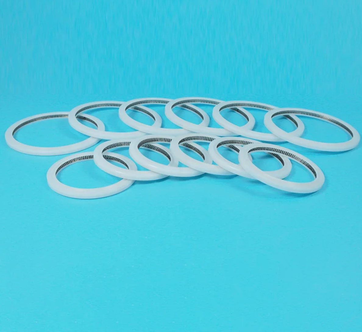
Most people see a spring energized seal as just a polymer jacket wrapped around a metal coil, but the real story is in how the two components argue with each other under load. The spring does not simply press the lip outward; it maintains a near-constant radial force as the jacket wears, creeps, or swells in aggressive chemicals. That force profile is tuned by changing the coil pitch, wire diameter, and cant angle, so the same seal family can behave like a soft feather at cryogenic temperatures or a stiff guard at 300°C. The jacket material then decides how much of that spring energy actually reaches the sealing interface, because a high-modulus polymer will transmit force differently than a soft PTFE blend.
The hidden part most design guides skip is the micro-slip zone at the dynamic lip. As a shaft rotates or reciprocates, the seal lip does not stay perfectly static against the counterface. It repeatedly sticks and releases on a microscopic scale, pumping a thin film of media under the lip to lubricate it, while the spring continuously pulls the lip back into contact when that film tries to escape. This balance between leakage and lubrication is not accidental; it is set by the lip’s undercut angle, the spring’s working range, and the surface finish of the hardware. A rough shaft can rip that micro-film apart, causing the lip to run dry and overheat, while an overly polished shaft can starve the interface and lead to stick-slip noise.
Pressure and temperature do not simply challenge the seal; they alter the spring’s contribution. At high external pressure, the system pressure itself energizes the jacket, so the spring becomes a secondary insurance policy that mainly matters during low-pressure start-up and thermal cycling. In vacuum service, that relationship flips: the spring is the only source of lip loading once the atmosphere is removed. Recognizing when the spring is doing the heavy lifting versus when the media pressure takes over is what separates a seal that survives one validation test from one that holds for years in a barely documented corner of a chemical plant.
PTFE Jacket Compounds Built for Chemical Onslaught
When aggressive acids, solvents, and oxidizing agents are part of daily operations, standard cable jackets quietly surrender. PTFE jacket compounds take a different path entirely. Their carbon-fluorine backbone resists nearly every chemical thrown at it, from concentrated sulfuric acid to hot sodium hydroxide. Even after months of immersion, the jacket retains its integrity, dielectric strength, and flexibility—no swelling, no cracking, no loss of surface resistivity.
What sets these compounds apart is not just chemical inertness but how that property is engineered into a workable jacketing material. Unlike extruded coatings that rely on plasticizers or additives vulnerable to attack, PTFE compounds are designed to be processed into thin, uniform jackets that hug tight-bend radii without sacrificing protection. The result is a cable that survives in places where polyurethane and PVC turn brittle or dissolve, from chemical reactor wiring to downhole instrumentation.
Field reports keep confirming the same story: cables jacketed with PTFE compounds outlast alternatives by a factor of five or more in chlorine plants, pickling lines, and solvent recovery systems. Their ability to shrug off chemical onslaught also means fewer shutdowns for cable replacement, lower risk of insulation failure, and a much longer service life in environments that chew through conventional materials.
Designing for Pressure, Temperature, and Motion Extremes
Environmental loads rarely arrive one at a time. A connector in a subsea wellhead may see 15,000 psi while thermal cycling swings the housing by 100°C, and vibration from riser motion keeps working on the seals. The practical starting point is not selecting a stronger material but mapping where stress, thermal expansion, and dynamic displacement overlap. That overlap often lives in the transition zones: at threads, weld roots, or the edge of a molded boot. Design reviews that treat pressure, temperature, and motion as separate ratings miss the combined damage mechanism.
Thermal extremes change clearance, preload, and lubrication. At cryogenic temperatures, elastomers lose compliance and shrink faster than surrounding metals; at high temperatures, creep relaxes the very preload that keeps a joint sealed. Motion extremes add fatigue, fretting, and impact. A useful tactic is to design in strain relief or isolation at interfaces, then verify with combined-environment testing rather than sequential tests. For example, run a thermal cycle under full working pressure while applying the expected motion profile. That reveals leaks and loosening that individual tests hide.
Material selection follows from the failure mode, not the datasheet headline. High-strength alloys may resist pressure but become brittle when cold, while tough polymers may not survive continuous flex at 200°C. The better approach is to define the envelope: what is the worst simultaneous combination of pressure, temperature range, and motion amplitude/frequency? Then choose materials and geometry with enough margin in that combined envelope. Prototype early with representative samples, because finite element models struggle to capture friction changes, seal extrusion, and wear particles in the same run.
Custom Seal Profiles That Match Real Operating Conditions
Real operating conditions rarely stay inside the narrow boundaries used to rate standard seals. A housing that flexes under load, a shaft that runs slightly eccentric at temperature, or a fluid that thins out during start-up can push a generic profile into early leakage. Custom seal profiles are developed around these specifics, with cross sections adjusted to the measured surface finish, gland distortion, pressure cycling, and even the direction of any residual shaft movement. That detail matters more than most catalog ratings suggest.
Rather than starting with a known shape and tweaking a lip angle, a custom profile often begins with failure data from the application itself. Finite element work and short-run prototypes can reveal where a standard geometry would pinch, fold, or lose interfacial pressure. The result might be an asymmetric heel, a variable interference band, a spring groove relocated to follow a wear pattern, or a dual-hardness cross section that keeps a soft lip stable under high side load. These are design decisions that only make sense against a specific set of operating data.
When the profile matches the actual duty cycle, the difference shows up in seal life, energy draw, and the frequency of unplanned maintenance. A well-fitted custom seal does not simply last longer; it behaves predictably as conditions shift, holding a consistent contact patch instead of overloading one edge. For equipment that runs hot, dirty, or irregularly, that predictability is often the factor that separates a nuisance leak from years of quiet service.
From Deep Wells to Vacuum Chambers: Proven in the Field
Real-world validation doesn't come from a spec sheet. It comes from years of operating inside boreholes where pressure, temperature, and vibration leave no room for error. Our equipment has logged thousands of hours in deep well installations, often in conditions that force other systems offline within days. Those same core components, refined through repeated field cycles, now sit at the heart of our vacuum chamber line.
That continuity matters more than most people expect. A seal that survives a downhole pulser isn't just durable; it has already proven it can handle thermal shock, chemical exposure, and mechanical fatigue. When we adapted the design for high-vacuum environments, we didn't start from scratch. We started from a platform that had already earned its place in the field, then tuned it for cleanliness, outgassing, and leak-tight performance.
The result is a component family that carries its history with it. Whether it is keeping a sensor alive at 8,000 feet below the surface or maintaining a stable pressure boundary in a research chamber, the same principles apply: build it to survive the worst day, and the typical day takes care of itself.
FAQ
The combination of a corrosion-resistant PTFE jacket and a resilient metal spring allows these seals to maintain a reliable lip seal even when temperature swings, pressure spikes, or chemical exposure would degrade conventional elastomers. The PTFE jacket provides a low-friction, chemically inert sealing surface, while the spring compensates for wear, creep, and hardware misalignment.
The spring acts as a live-loading element that continuously pushes the PTFE lips against the mating surface. Unlike O-rings that can lose compression set, the metal spring retains its deflection for the life of the seal, so even as the PTFE wears or undergoes cold flow, the contact stress stays above the minimum required for a tight seal.
You'll find these seals in oil and gas, chemical processing, pharmaceuticals, food and beverage, semiconductor manufacturing, and cryogenics. They are particularly valued in valves, pumps, mixers, and rotary unions where aggressive media, wide temperature ranges, or strict purity requirements rule out standard rubber seals.
Depending on the service, we offer virgin PTFE for maximum chemical resistance, glass-filled for higher wear resistance, carbon-filled for improved thermal conductivity and extrusion resistance, and food-grade PTFE for FDA-compliant processes. Each compound can be paired with different spring materials like 316 stainless steel, Elgiloy, or Hastelloy to match the environment.
Yes, we regularly engineer seals for existing hardware that doesn't meet standard gland sizes. By adjusting the PTFE jacket profile, lip geometry, and spring load, we can fit seals into shallow, wide, or worn grooves without modifying the mating components, which often saves our customers the cost of re-machining.
Typical operating range spans from -200°C to +260°C (-328°F to +500°F), but with specialized PTFE blends and spring alloys, we've validated seals for cryogenic service down to -268°C and brief excursions up to +300°C. The spring material and PTFE grade must be selected together to avoid loss of spring force at temperature extremes.
For high-pressure service, we use back-up rings or modify the PTFE geometry to prevent extrusion into the clearance gap. In vacuum systems, the spring keeps the PTFE lip in contact with the shaft even at very low differential pressures, which helps maintain a tight seal where traditional lip seals would leak. Pressure ratings from 10^-6 Torr vacuum to over 750 bar are achievable with the right design.
Conclusion
When temperatures swing, pressures spike, or aggressive chemicals attack, conventional seals tend to fail in predictable ways—they lose elasticity, cold-flow, or get chewed up at the lip. A spring energized PTFE seal replaces that fragile equilibrium with a metal spring that keeps a constant radial load on the jacket, even as the PTFE wears or creeps. The right manufacturer doesn't just swap materials; they formulate PTFE compounds with fillers like glass, carbon, or graphite to stand up to chemical onslaught, and they design the seal cross-section around real pressure, temperature, and motion extremes rather than relying on off-the-shelf geometries. This isn't a generic seal with a spring added; it's an engineered system where the jacket material, spring rate, and geometry all work together to maintain a seal long after traditional options have failed.
That mindset carries into custom profiles: grooves, lips, and spring cavities are matched to actual operating conditions, not generic catalogs. Field history backs it up—from deep oil wells where sour gas and brutal thermal cycles destroy ordinary seals, to vacuum chambers that demand near-zero outgassing and leak rates. The best spring energized PTFE seal manufacturers treat each application as its own problem, using proven combinations of jacket compound, spring force, and profile geometry to keep sealing where others crack, shrink, or extrude. That field-proven record is why engineers specify these seals for critical service instead of accepting frequent rebuilds or unplanned downtime.
Contact Us
Contact Person: Tommy Xiao
Email: [email protected]
Tel/WhatsApp: 8615651509888
Website: https://www.ptfe-factory.com