
Walking Beam Quenching and Tempering Production Line for Oil Well Pipes Explained
2026-09-12
Oil well pipes live hard lives. They're slammed by pressure, corroded by sour fluids, and cycled through brutal temperature swings. Yet they still need to hold up for decades. That's where the walking beam quenching and tempering line comes in—a continuous heat-treatment system that locks in the strength and toughness these tubes demand. At THINKING-LONG, we've engineered this process to handle the full range of oil country tubular goods, from casing to drill pipe, with uniform heating and precise cooling. But what makes this line different from a standard batch furnace? And why does walking beam motion matter for pipe quality? Read on to see how the right quenching and tempering setup turns raw steel into well-ready products.
The Walking Beam Mechanism and Its Role in Pipe Transfer
At the core of many pipe transfer lines, the walking beam mechanism uses a pair of stationary beams and a set of movable beams to move pipes forward in a controlled, step-by-step rhythm. During each cycle, the movable beam rises between the fixed supports, lifts the pipe clear of its cradle, advances horizontally by a preset distance, and then lowers the pipe back onto the stationary beam. After lowering, the movable beam retracts to its starting position below the pipe level, ready for the next lift. This rectangular motion pattern prevents pipes from rolling or banging against one another, making the transfer predictable even with heavy wall tubes or long lengths.
Compared with roller conveyors, the walking beam design offers gentler handling and tighter control over pipe spacing. Each pipe rests in a machined or fabricated saddle, often V-shaped or contoured to match the outer diameter, which keeps round sections from drifting sideways. Because the pipe is lifted vertically before any forward movement occurs, there is no sliding contact between the pipe body and the beam surface. This is particularly valuable for coated, stainless, or high-alloy pipes where surface scratches or dents are unacceptable. The stroke length and lift height can be adjusted to suit different diameters, allowing the same line to process a wide product mix without changing tooling.
In a continuous finishing or inspection line, the walking beam also acts as a buffer or positioning station. The step frequency can be tied to the cycle time of a downstream straightener, hydrotester, or cut-off saw, so pipes arrive exactly when the machine is ready to accept them. If the downstream equipment pauses, the beam simply stops stepping while pipes remain safely nested in their saddles. This creates a natural accumulation zone without the risk of end-to-end collisions. Operators can tune the motion profile—short quick steps for light tubes, longer slower strokes for heavy casing—so the same mechanism handles a broad range of products without sacrificing reliability.
Quenching Parameters That Influence Hardness and Straightness
The choice of quenchant directly shapes the cooling curve, and that curve decides how deep the martensitic layer goes. Fast oils or polymer solutions pull heat away quickly enough to boost surface hardness, but they also raise thermal gradients across the section. Those gradients are what cause bowing and twisting once the part relaxes. A slower medium like hot oil or molten salt narrows the temperature difference between the core and the surface, which keeps distortion lower at the cost of some hardness.
Agitation matters just as much as the fluid itself. Uniform flow around the part prevents vapor blanket collapse from becoming uneven, a common source of soft spots and irregular straightness. Directed jets can be tuned to cool thicker sections more aggressively while shielding thin flanges, letting the whole component transform more uniformly. Without that balance, the first areas to reach martensite start contracting while neighboring zones are still expanding, setting up residual stresses that show up later as warp.
Quench temperature and holding time before quenching also set the stage. A lower austenitizing temperature reduces the driving force for distortion because there is less thermal contraction to manage during the drop. Interrupted quenching or time-controlled quenching in a second bath allows the part to equalize near the martensite start temperature, which can straighten out some of the early thermal stresses before the final transformation locks in the shape.
Tempering Cycles for Uniform Strength in Oil Well Pipes
Uniform strength in oil well casing and tubing rarely comes from a single tempering pass. The pipe wall cools at different rates after quenching, leaving a gradient in as-quenched hardness that a well-designed tempering cycle has to level out. Practical heat treatment often uses a stepped or two-stage temper: the first hold at a lower temperature relaxes the highest-stress regions without overtempering the mid-wall, and a slightly higher second stage brings the entire cross-section to the same target yield range. Soak time is adjusted to wall thickness, not just set from a generic chart.
Furnace loading matters as much as the setpoint. If pipes are stacked too densely or placed near the burner, surface thermocouples can read the target temperature while the inner rows lag by thirty or forty degrees. Longer stabilizing holds, recirculation fans, and rotation of the load help narrow that spread. Some mills also run a short normalization-style reheating before final tempering to erase residual stress patterns from straightening or cold sizing, which otherwise show up as inconsistent hardness along the pipe length.
The final check is not just average hardness but scatter. A useful acceptance practice is to sample both ends and mid-length on the same pipe, plus the inside and outside surfaces at each location, and require the spread to stay inside a narrow band rather than just meet a minimum value. This catches uneven tempering before the pipe goes into a well where local soft spots can reduce collapse resistance or local hard zones can become initiation sites for sulfide stress cracking.
Loading, Heating, and Transfer: Where Throughput Is Decided
Throughput rarely hinges on the headline cycle time; it gets quietly eaten during loading and transfer. Manual loading can look fast on paper, but the real cost shows up as inconsistent part orientation, missed sensors, and operators who can’t match a robot’s rhythm hour after hour. Even a half-second delay per cycle compounds into lost shifts over a month.
Heating is the second place where throughput slips away. Oversizing the heater to force faster ramp-up often backfires—thermal overshoot damages material or warps thin sections, forcing rework that negates any time saved. The better approach is to tune the heating profile to the mass and thermal conductivity of the part, not to chase an arbitrary target temperature.
Transfer between stations is where most lines lose 8–12% of their nominal throughput without anyone noticing. A slight pause to verify alignment, a worn gripper that needs a second attempt, or a conveyor speed mismatch all stack up. The highest-leverage change is usually not a faster robot but a transfer path with fewer dead stops and more overlap between heating and loading windows.
Sensors and Automated Adjustments During Heat Treatment
During heat treatment, thermocouples embedded in the workload or placed in close proximity deliver real-time temperature readings, while atmosphere sensors track carbon potential or oxygen levels to control carburizing and decarburizing reactions. These measurements feed directly into the furnace's control loop rather than being logged for later review.
When sensor data drifts from the programmed cycle, the automated adjustment system responds immediately. A lagging zone receives increased power to its heating elements; an overly rich atmosphere triggers a reduction in enrichment gas flow. This closed-loop response manages multiple interacting variables without operator intervention, and modern controllers even compensate for thermal inertia by anticipating corrections before deviations occur.
Meeting Oil Country Tubular Goods Specifications on One Line
Running casing, tubing, and drill pipe through a single production line used to force compromises in wall thickness, grade, and threading. Not here. The line is configured with inline quench-and-temper stations, multi-axis CNC threading, and automated drift testing, so a J55 upset tube can shift to a Q125 integral-joint casing string without a separate batch run. Dimensional checks occur after each forming step, not just at final inspection, which keeps API 5CT and 5L tolerances locked in from end to end.
Thread profiles, from API BTC and EUE to semi-premium and premium connections, are cut on the same transfer path but verified with individual gauges and phosphor-oil pressure tests at the coupling station. If a joint trips a leak threshold, it is sidelined before the next piece enters the line. That means mixed schedules—say N80 tubing with P110 casing—don't stall for retooling or waiting on lab results.
The payoff shows up in mill traceability. Each pipe carries a heat-number laser mark tied to its chemistry, heat treatment curve, and torque-turn data, so a customer inspecting a finished bundle can match every length back to a single continuous record. Meeting OCTG specifications on one line is less about machine speed and more about keeping the variables visible and controlled from raw tube to rack-ready product.
FAQ
It's a continuous heat treatment system where pipes move through the furnace and quench on a walking beam mechanism, which lifts and advances them in steps. This design keeps pipes separated, ensures uniform heating, and prevents surface damage compared to roller hearths.
Oil well pipes must handle high internal pressure, corrosive fluids, and mechanical stress deep underground. Quenching creates a hard martensitic structure; tempering then reduces brittleness and tunes the strength-toughness balance, so the pipe can survive harsh downhole conditions without failing.
A roller hearth continuously rotates pipes, which can cause skid marks or uneven contact heating. A walking beam lifts the pipe off the stationary supports, moves it forward one pitch, and lowers it back. This stepwise motion eliminates rotation, preserves surface finish, and allows precise control of residence time in each zone.
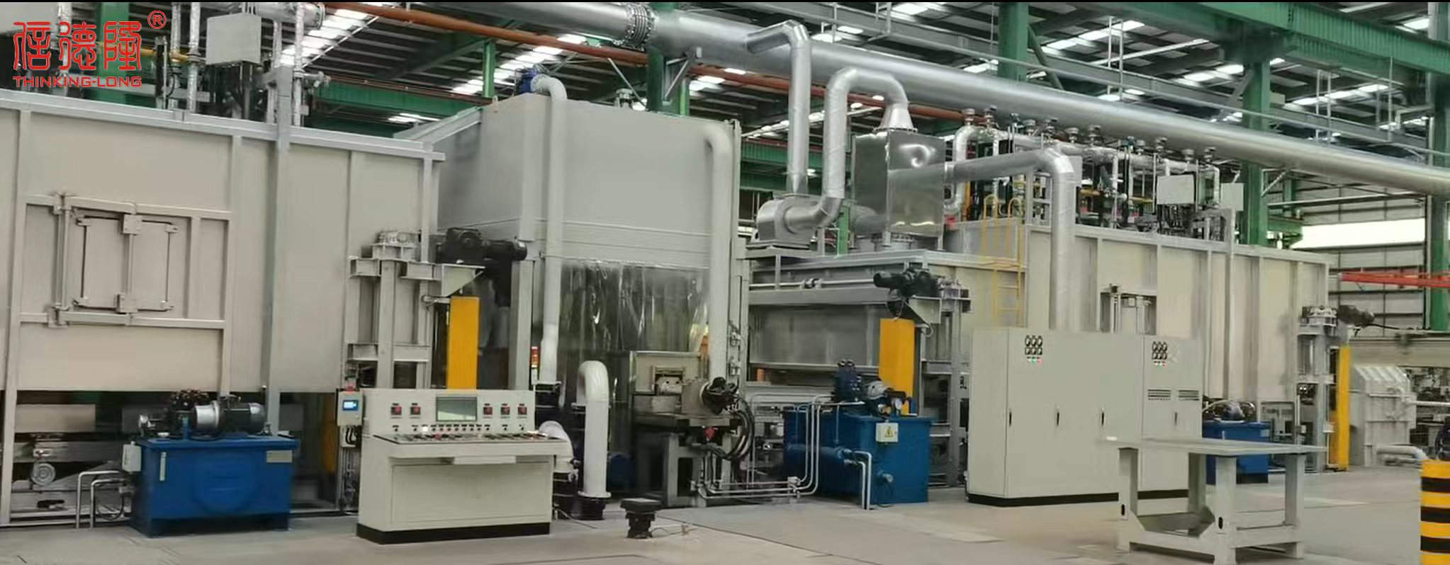
Typically you have loading, austenitizing furnace, quenching unit (water or polymer), tempering furnace, cooling section, and unloading. The walking beam carries pipes through each furnace zone, then the quench is often done by rapid immersion or spray while the pipe is transferred.
Grades like J55, N80, L80, P110 for casing and tubing often undergo quench and temper to meet API 5CT requirements. The exact parameters depend on the steel chemistry, wall thickness, and target yield strength.
Furnace zones are independently controlled, and the walking beam design ensures pipes are spaced rather than packed together. Some lines rotate the pipe periodically or use baffles and burner tuning to even out temperature. But the stepwise advance itself reduces cold spots because pipes are not in continuous contact with the beam.
Water is common for fast cooling, but polymer solutions or oil may be used to control cooling rate and reduce distortion or cracking. The quench system often includes high-pressure sprays or immersion tanks with agitation, and the walking beam can lower the pipe into the quench bath smoothly.
Attention to beam design, furnace atmosphere, quench transfer time, and automation. A good line minimizes transfer time from furnace to quench to avoid missing the critical cooling rate, uses alloy-specific recipes, and has built-in monitoring for temperature and motion sync.
Conclusion
A walking beam quenching and tempering line handles oil well pipes by moving them through the furnace and quench using a repeated lift-advance-lower cycle. This mechanism keeps tubes spaced apart, prevents point-contact damage, and allows predictable heat exposure. Throughput is largely set during loading, heating, and transfer: pipe diameter, wall thickness, and charge density determine furnace residence time, while beam stroke speed and synchronization affect how evenly each joint reaches austenitizing temperature. Quench parameters then take over. Water or polymer flow rate, pressure, and spray pattern must be tuned to harden deeply enough without causing bows or cracks. Rotation during quenching and controlled entry angles help keep straightness within tolerance, since uneven cooling on one side can create residual stress that later shows up as warp.
After quenching, tempering cycles are adjusted to relieve some of that stress and bring strength and toughness into the required range for oil country tubular goods. Longer temper times or multiple heat zones handle thicker walls, while sensors track tube surface temperature, quench bath temperature, and transfer timing to trigger automated corrections. If a batch drifts toward high hardness or excessive distortion, the control system can tighten spray pressure or slow the beam. This closed-loop approach lets a single line meet API 5CT and similar specifications for hardness, tensile strength, Charpy impact energy, and straightness without separate off-line rework. Recipe storage also shortens grade changes, so the same walking beam system can switch between casing, tubing, and drill pipe with minimal downtime.
Contact Us
Contact Person: Qian Xijun
Email: [email protected]
Tel/WhatsApp: 8613961736750
Website: https://www.thinkinglong.com/